
| Home | S-100 Boards | History | New Boards | Software | Boards For Sale |
| Forum | Other Web Sites | Quiz | Index |
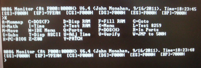
| Section 1. | This is a classical monitor. Display, Change RAM/ports etc. |
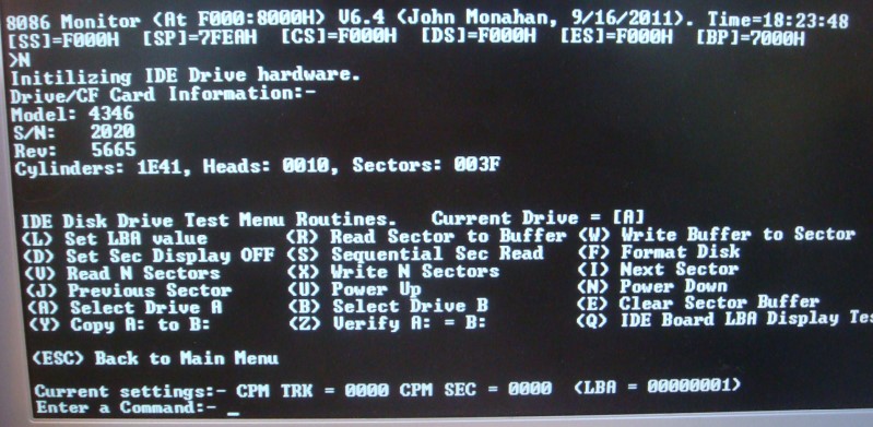
| Section 2. | This is a self contained set of routines run diagnostic tests on the S100Computers/N8VEM IDE board. |
| Section 3. | This fairly complex section. It emulates most of the IBM-PC ROM BIOS interrupts (hard & soft) such that MS-DOS (V4.01)/FreeDOS can be run on the system - without DOS modifications. |
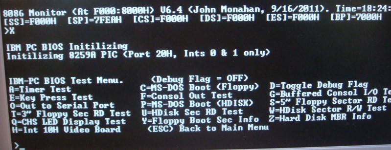
AH = 02h
AL = number of sectors to read/written (must be nonzero)
CH = low eight bits of cylinder number
CL = sector number 1-63 (bits 0-5). The high two bits are for cylinder bits 6-7. (hard disk only)
DH = head number
DL = drive number (bit 7 set for hard disk)
ES:BX -> data buffer
This page was last modified on 09/19/2011